VPC Components Deep Dive
VPC Components Deep Dive
VPC Layout
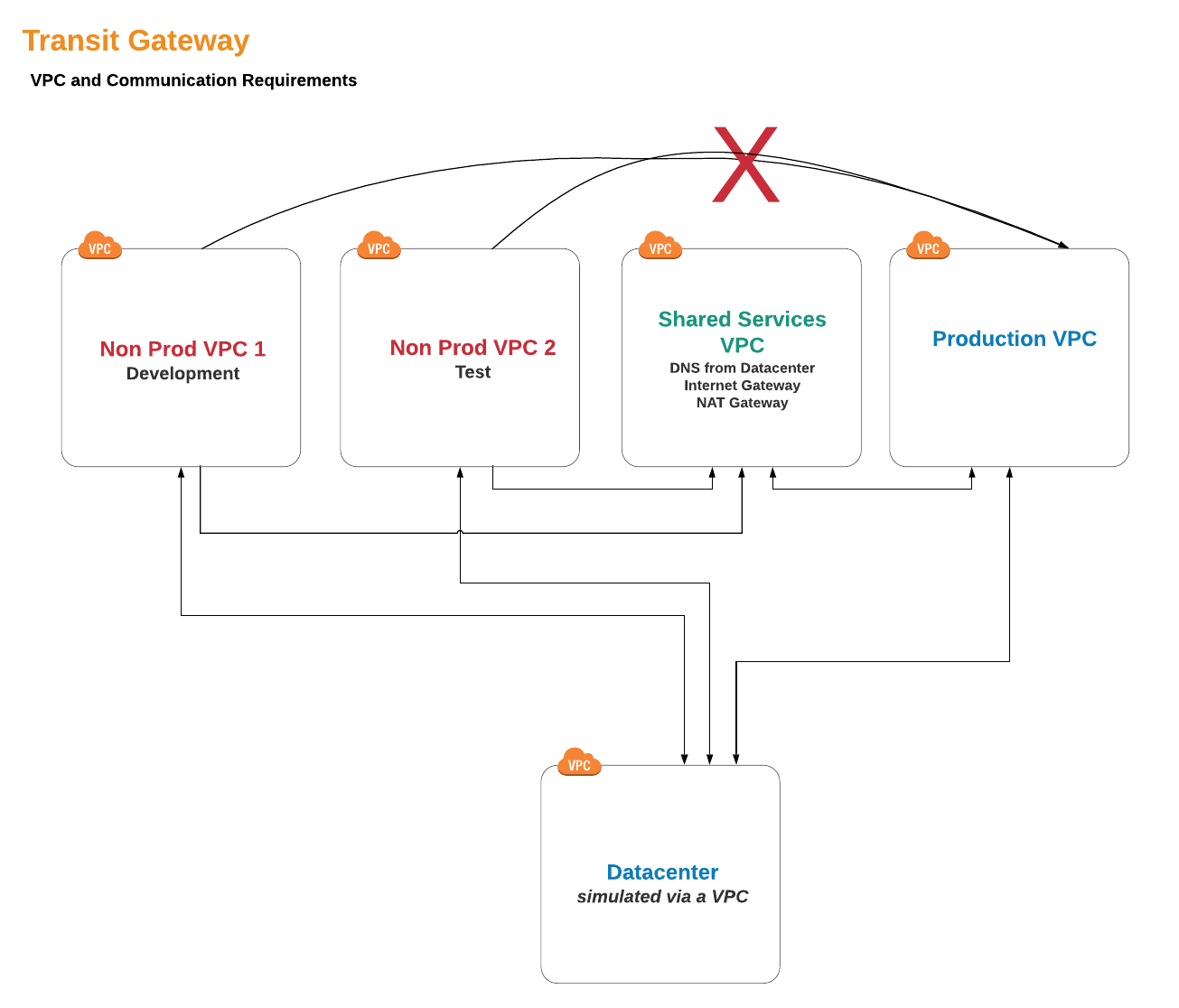
We are going to provide three types of VPCs:
- Non-production VPCs: We will create some of these to house our Test and Development resources.
- Production VPCs: This is for our live production systems.
- Shared Resources: For resources and services that should be accessible across all VPCs.
In addition, we need a VPC to represent our on-premise environment, a simulated Datacenter:
- Datacenter: In the real world, this would be our existing Datacenter or co-location facility with all the hardware contained, but we are going to make our own version in the cloud!
IP Addressing
Carving up and assigning private IP address space (RFC 1918 addresses) is a big subject and can be daunting if you have a large enterprise, especially considering large business events with network impact, such as company mergers. Even when you have a centralized IP address management system (IPAM), you will find undocumented address space being used and sometimes finding usable ip space is difficult. However, as network professionals, we want to find large non-fragmented spaces so we can create a well-summarized network. Don’t laugh: we got into this because we like challenges, right?
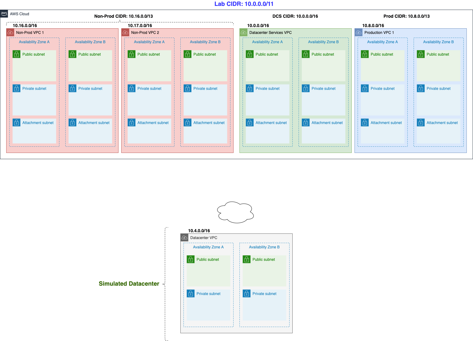
- Non-Production CIDR: 10.16.0.0/13 (10.16.0.0 to 10.23.255.255). For this lab, we will fragment 10.16.0.0/13 into smaller Non-Production VPCs: 10.16.0.0/16 and 10.17.0.0/16. The remaining ip space is left untouched for future growth.
- Production CIDR: 10.8.0.0/13 (10.8.0.0 to 10.15.255.255). For this lab, we will only use 10.8.0.0/16 for the Production VPC. The remaining ip space is also left untouched.
- Shared Services CIDR: 10.0.0.0/16 (10.0.0.0 to 10.0.255.255).
We will also carve out a /16 CIDR for our Datacenter VPC Addressing:
- Datacenter VPC CIDR: 10.4.0.0/16 (10.4.0.0 to 10.4.255.255). which will be our Datacenter VPC.
-
Go to VPC
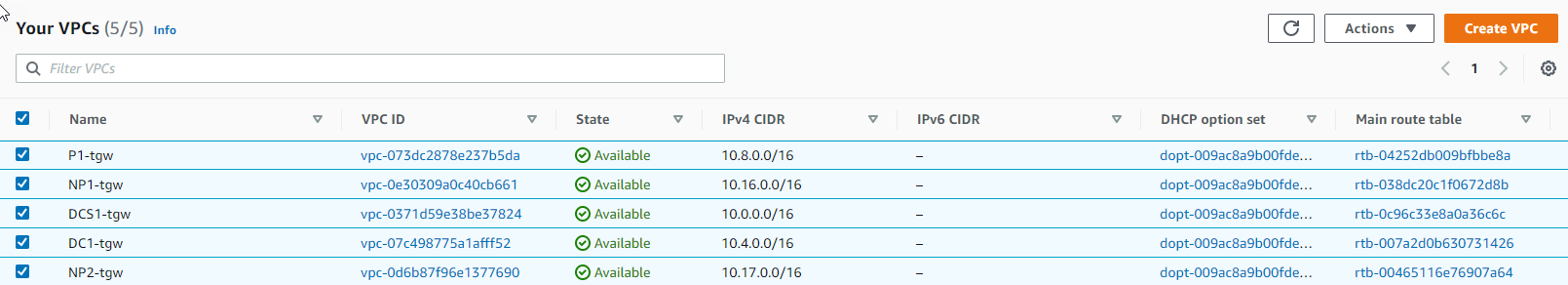
- Observe we have created 5 VPCs in the Available state
- P1-your_stack_name (This is our Production VPC)
- NP1-your_stack_name (This is our Non-Production VPC number 1, a.k.a Development VPC)
- NP2-your_stack_name (This is our Non-Production VPC number 2, a.k.a Test VPC)
- DCS1-your_stack_name (This is our Shared Services VPC)
- DC1-your_stack_name (This is our Datacenter On-premise VPC)
-
Then go to Subnet. We have partitioned each VPC into multiple subnets. For example, the Production VPC is partitioned into 6 subnets (3 subnets per Availability Zone). Each subnet has its own portion of the VPC CIDR range.
- Observe about 30 subnets including Private and Public
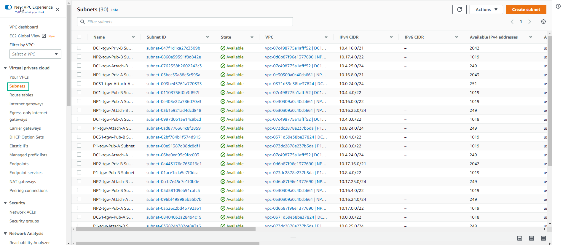
Subnets are associated with Route Tables, which govern how traffic routes within the subnet. You will notice for example that both NP1-your_stack_name-Priv-A Subnet and NP1-your_stack_name-Priv-B Subnet share the same route table: NP1-your_stack_name-Private Route Table. And this route table has only a route for the local VPC CIDR block. This means that any instance present in this subnet will only have routing in that range. We will be changing that in the next lab, so that you can route outside of the NP1 VPC.
-
Go to Route table
- Observe that there are about 20 Route tables assigned to the subnets.
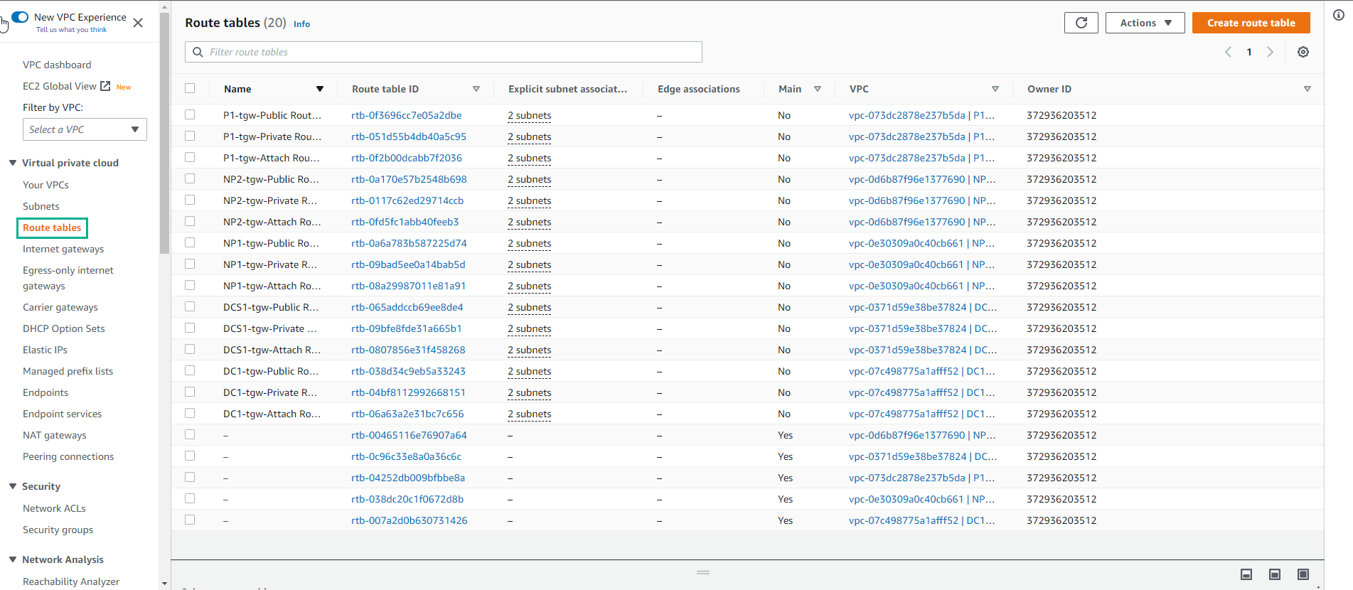
As a last comment in this section, the “Attachment” subnets are intended to serve as the Transit Gateway attachment subnets. This is a Transit Gateway best practice as the Transit Gateway will position its own Elastic Network Interface in the subnet in order to communicate with any VPC resource. Creating dedicated subnets for Transit Gateway VPC attachments gives you total control about how to route traffic coming from the Transit Gateway into the VPC.
-
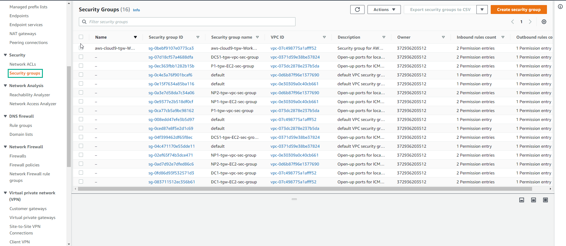
Go to Security Group to view the created security groups. Security Groups act as a virtual firewall for your instances to control inbound and outbound traffic. They provide additional granularity while compared to NACLs:
-
Security Groups are associated with your EC2 instance ENIs
-
Security Groups are stateful
-
Security Groups are based on rules and only “allow” communications. As such, you can’t deny an specific communication with a security group rule.
-
Related to the previous item: as you can only “allow” communications, anything else is denied by default
-
There is no order defined for rule evaluation (opposite to the NACL statements, in which they go 1 by 1)
-
-
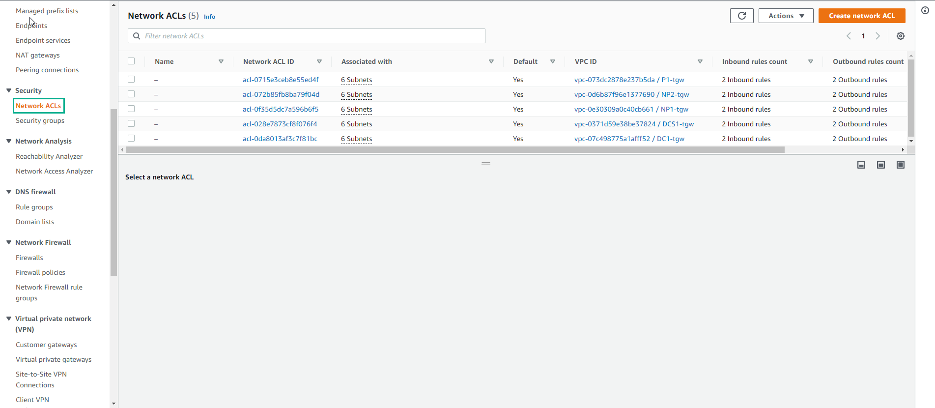
Go to Network ACLs. NACLs restrict traffic coming in/out of your subnets and constitute the first layer of defense you can define within the VPC:
-
NACLs are associated with subnets
-
NACLs are stateless. This means that you would need to define both “inbound” and “outbound” rules in order to allow traffic entering or leaving your subnets
-
NACLs are made of different statements, evaluated from top to bottom. Whenever there is a match, the evaluation is over
-
There is an implicit Deny at the end
-
- Go to Internet Gateway. An Internet gateway is a horizontally scaled, redundant, and highly available VPC component that allows communication between instances in your VPC and the Internet. It therefore imposes no availability risks or bandwidth constraints on your network traffic. Only 1 Internet gateway can be attached to a VPC at a given time. This virtual device is referenceable by the VPC routing tables. It acts as the edge device of your VPC.
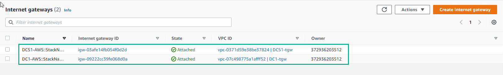
Internet Gateways are used along with “public subnets” to route traffic outside of your VPC. A “public subnet” is just a regular subnet attached to a Routing table in which there is a route towards an Internet Gateway.
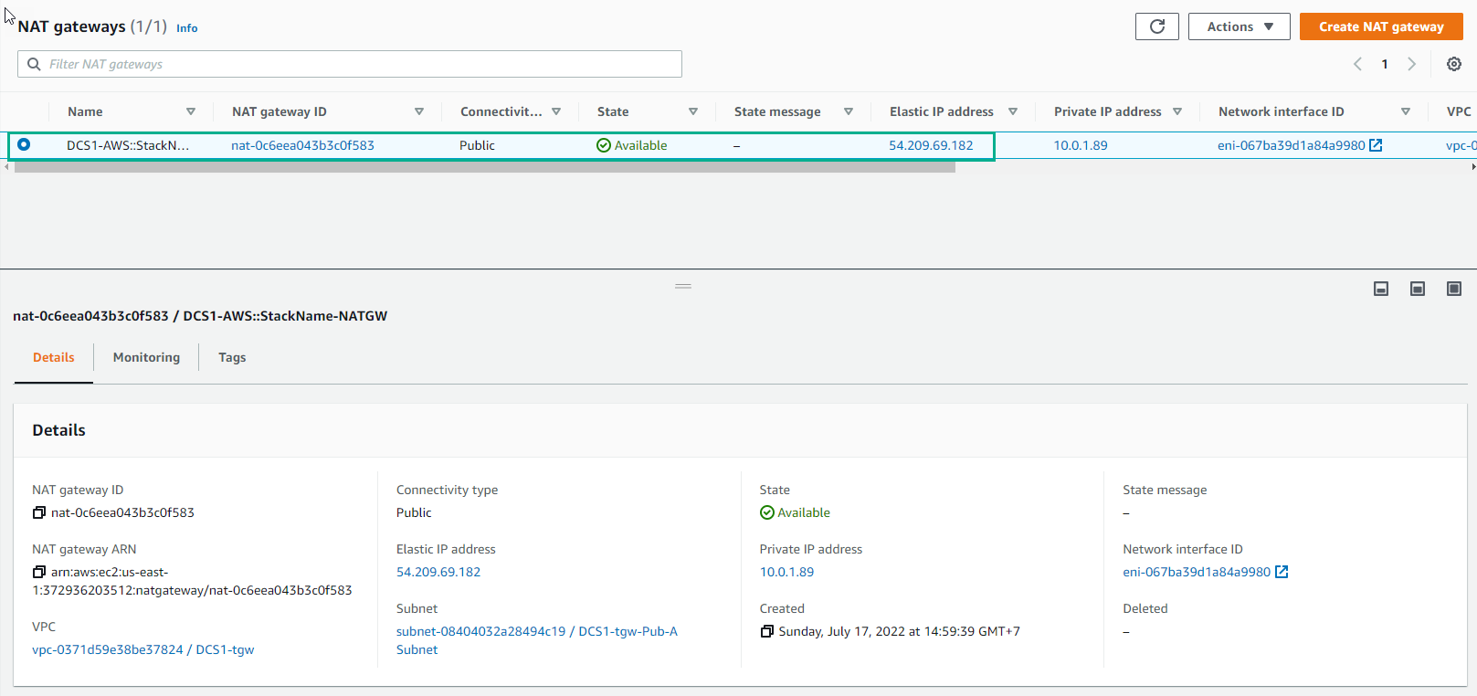
- Go to NAT Gateway. NAT Gateways are AWS managed devices that enable instances in a private subnet to connect to the Internet or other AWS services, but prevent the Internet from initiating a connection with those instances. There are 2 types of NAT Gateway connectivity: Public and Private. Public NAT Gateways are associated with public subnets, meaning that they also rely on Internet Gateways for their own Internet connectivity. Private NAT Gateways don’t route traffic via Internet Gateways and are intended for connectivity towards other VPCs or on-premise networks. Please take a look at the official documentation if you want to know more details about both NAT Gateway types. In this lab we will be using a Public NAT Gateway. This is the only NAT Gateway we have configured so far and it’s actually the same device we have seen on the previous section. Notice that is currently associated with a public subnet:
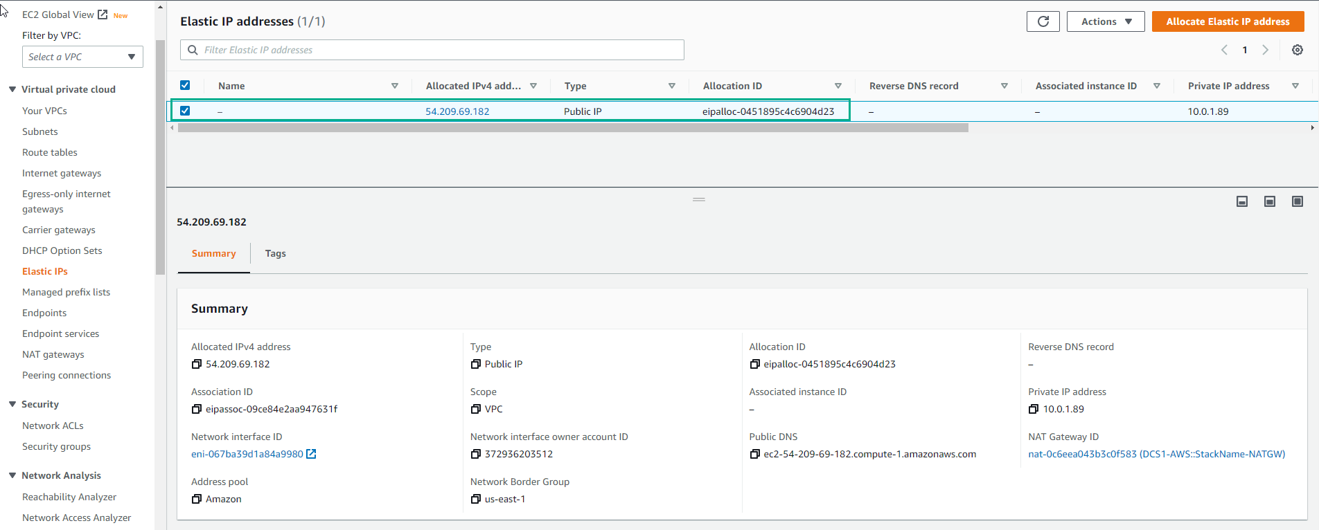
- Go to Elastic IP addresses. ENIs are widely used across many AWS resources, including EC2 instances. An ENI is a way to position a resource within a VPC, meaning reserving an IP for that resource to communicate within the VPC. As part of this deployment, CloudFormation has created several EC2 instances for us. Each of these EC2 instances will have one or more ENIs (depending on the size of the instance) within the subnet (VPC) they landed on. Navigate to the EC2 section of the console (browsing through Services -> EC2 at the top left) and locate the DCS1 server. Put a check in the box next to the server. In the page underneath you can see the subnet the server has been deployed to. If you click on the Networking tab you will be able to see the network interface details:
Connect Linux EC2 instance
-
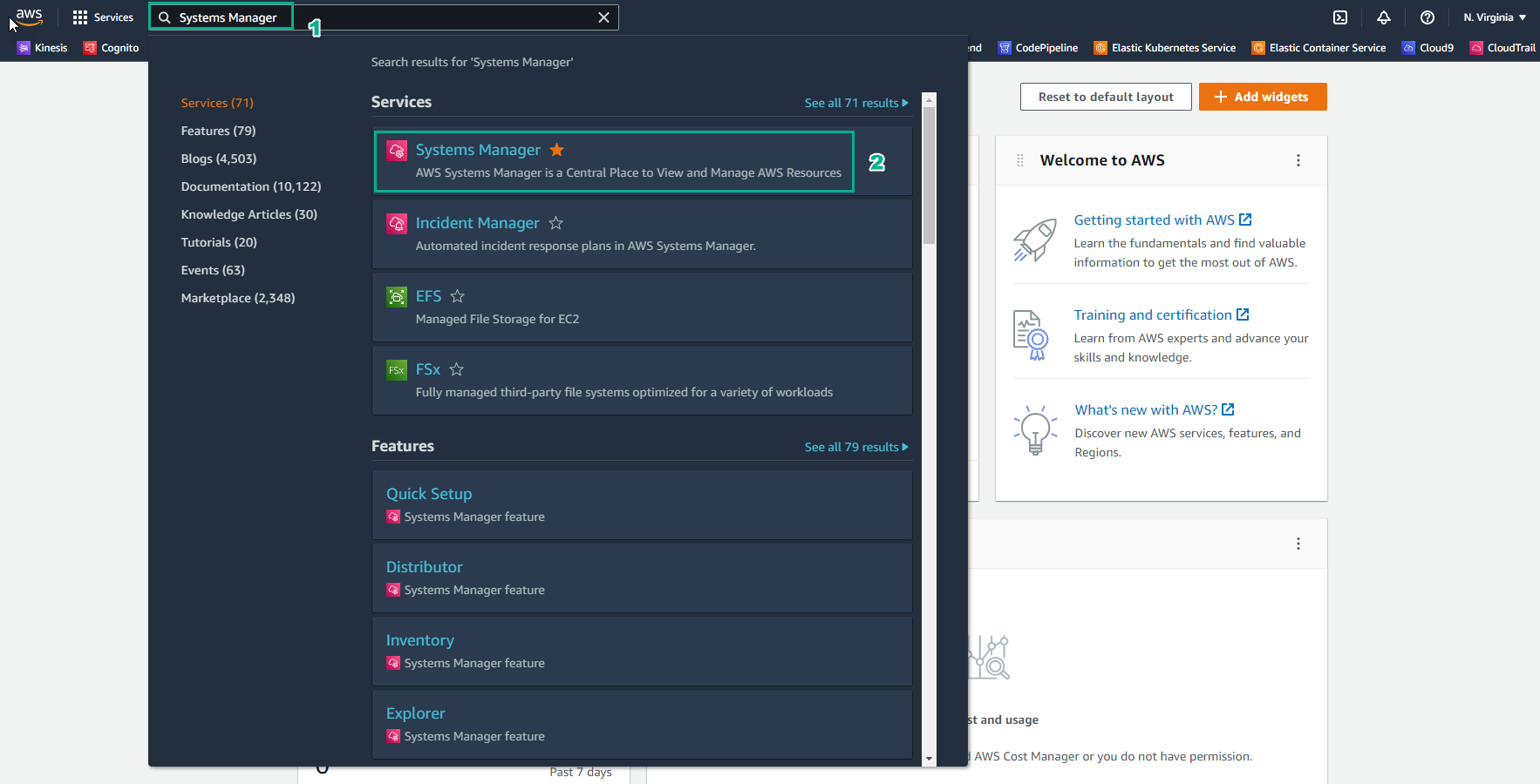
Go to AWS Management Console
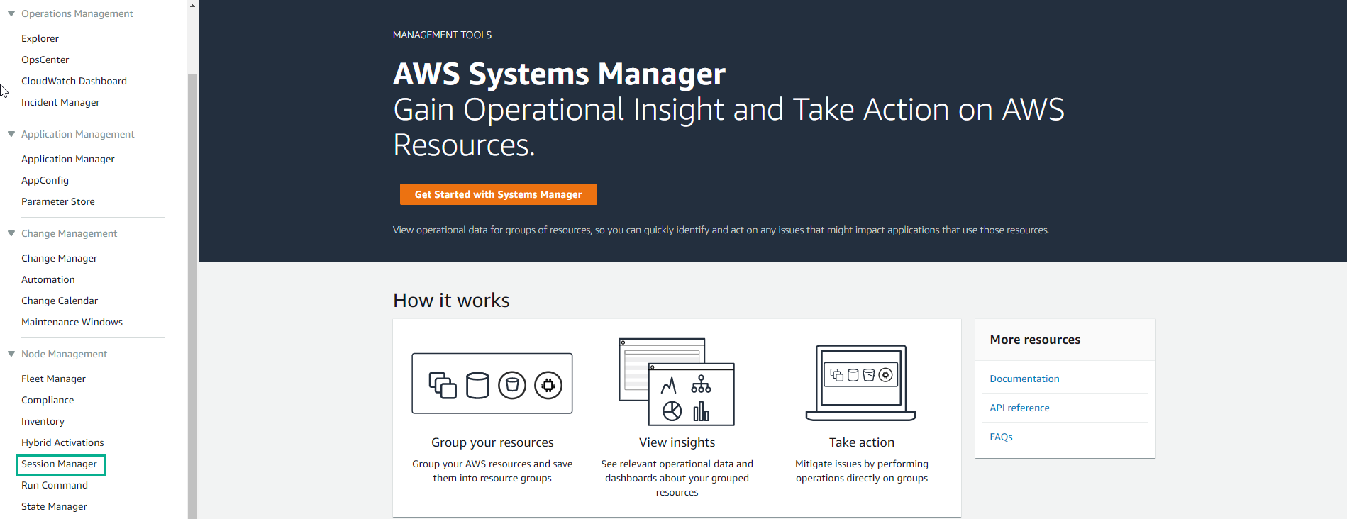
- Find System Manager
- Select System Manager. Systems Manager Gains Operational Insights and Takes Action on AWS Resources. We are going to take a look at just one of its many capabilities.
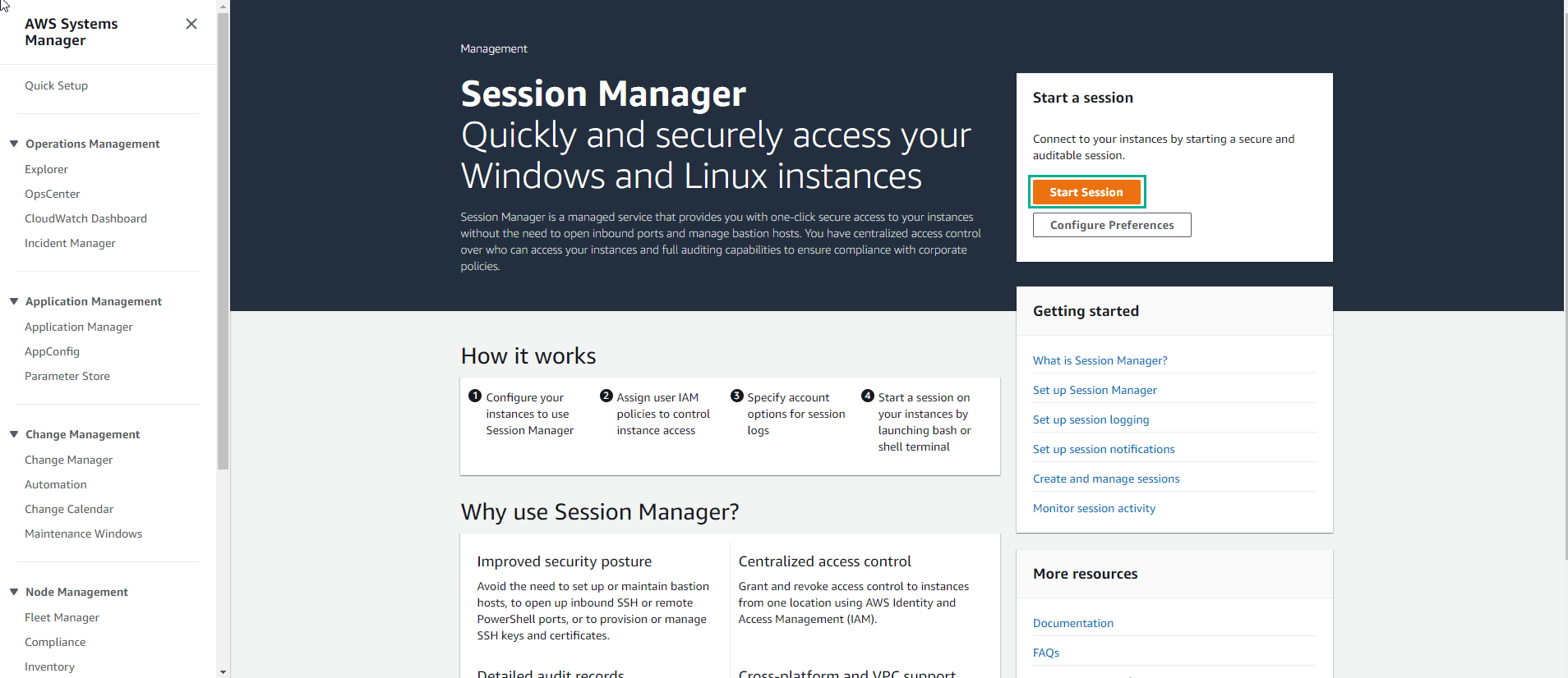
- In the System Manager interface, select Session Manager. Session Manager allows to using IAM roles and policies to determine who has console access without having to manage SSH keys for our instances.
- Select Start session
-
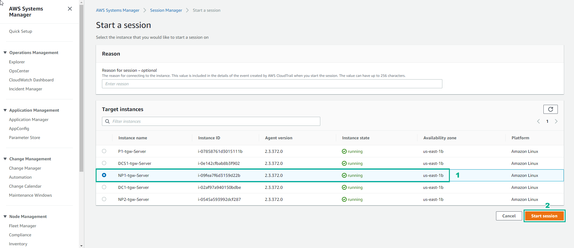
In the Start session interface
- Select NP1-tgw-Server
- Select Start session. Select the radio button next to the instance you wish to log into. You will now receive a Bash shell prompt for that instance.
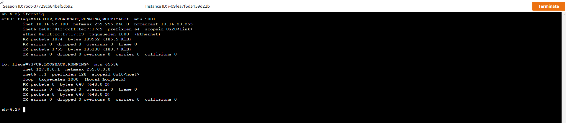
- In the interface NP1-tgw-Server session. Use the following command to check
ifconfig
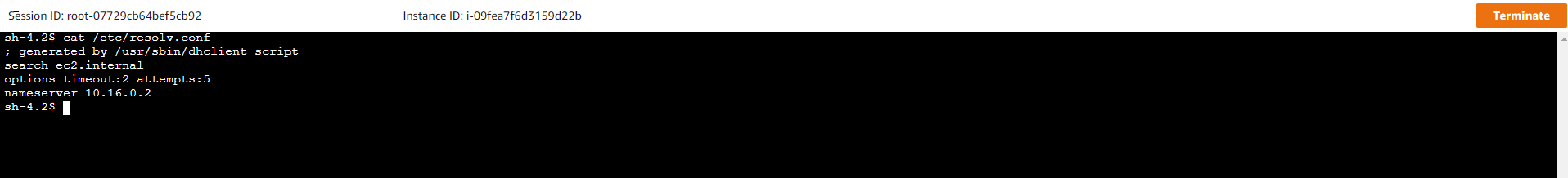
- Use the cat command
cat /etc/resolv.conf