Site-to-site VPN setup
Site-to-site VPN setup
What are we going to do? We will create two VPN tunnels from the Transit Gateway and connect them into a single instance of the Cisco CSR in the Datacenter VPC. This would simulate site-to-site VPNs between the AWS environment and your on-premise/HQ network. We are emulating a common VPN between AWS and the typical Cisco or any other router/firewall in your On-premise/HQ network:
In a real production environment we would setup a secondary router for redundancy and for additional bandwidth. Each VPN ipsec tunnel provides up to 1.25Gbps. While using multiple ipsec tunnels we can provide additional bandwidth with the use of ECMP (Equal cost multipath), meaning that all the tunnels will be used. On the AWS side, up to 50 parallel (ECMP) paths are supported. Many vendors support 4-8 ECMP paths, so check with your vendor in advance:
- Access the interface VPC
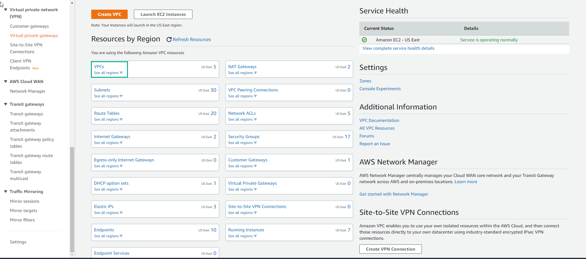
-
In the VPC interface
- Select Transit gateway attachments
- Select Crate transit gateway attachment
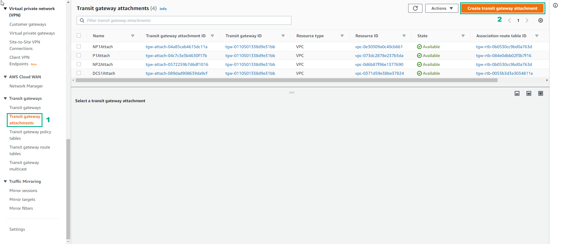
-
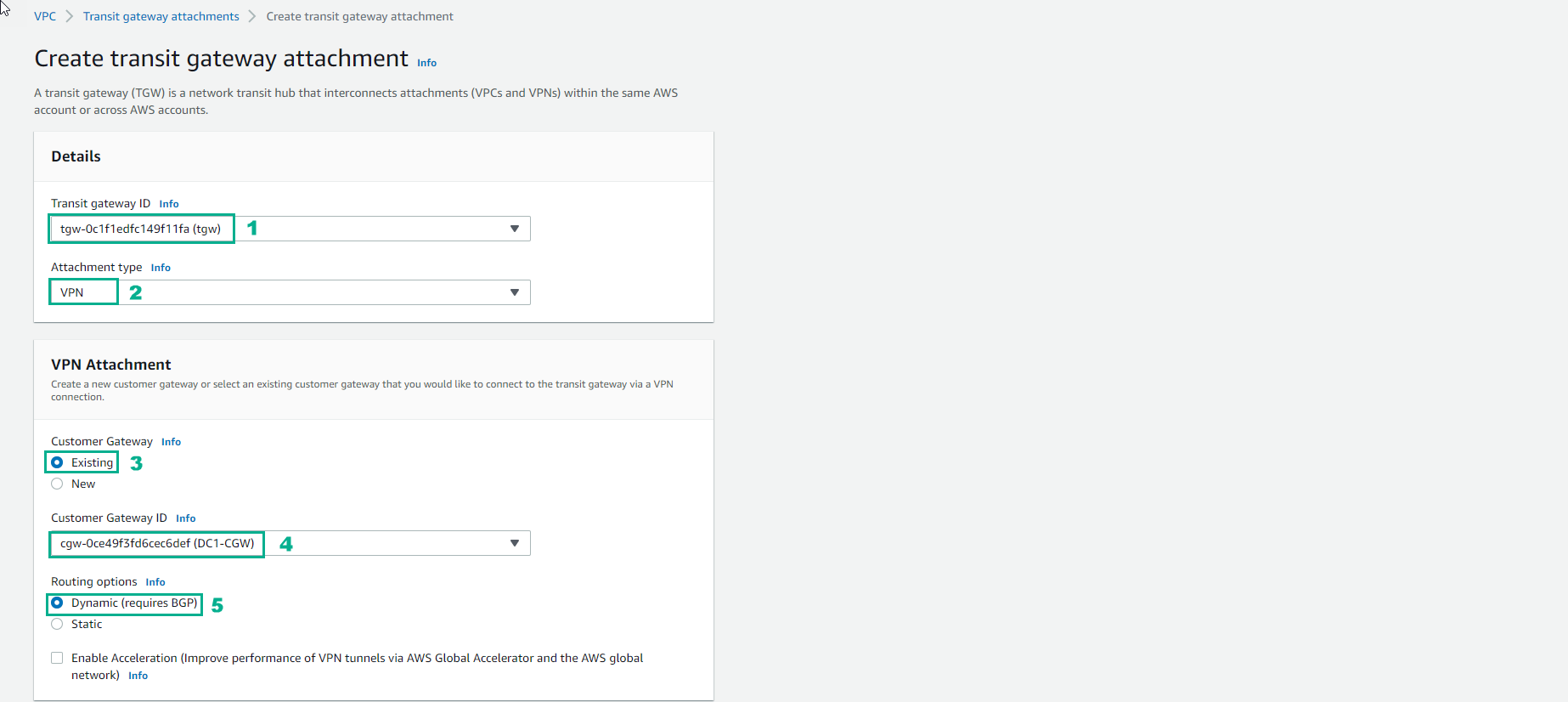
Perform configuration
- Transit Gateway ID refers to the Transit Gateway device already provisioned by the Cloudformation template
- Attachment Type is VPN
- Customer Gateway (CGW) will be Existing. Note: the CloudFormation template created the CGW. This is the IP address of our Datacenter VPN device and it matches the Elastic IP of the EC2 instance running the Cisco CSR.
- Customer Gateway ID (CGW) will be the available CGW ID in the drop down. This was created when we deployed the stack.
- Leave Routing options set to Dynamic(requires BGP). Note: BGP is required if you want traffic to balance across more than one VPN tunnel at a time (ECMP or Equal Cost Multipathing)
- Do not tick Enable Acceleration as we won’t be using it for this lab. However, for production environments GA delivers an enhanced VPN experience thanks to the use of anycast endpoints being advertised from our global network of points of presence (POPs)
- Configure the Tunnel
- For Inside IP CIDR for Tunnel 1 use 169.254.10.0/30 for CIDR.
- For Pre-Shared Key for Tunnel 1 use awsamazon
- For Inside IP CIDR for Tunnel 2 use 169.254.11.0/30 for CIDR.
- For Pre-Shared Key for Tunnel 2 use awsamazon
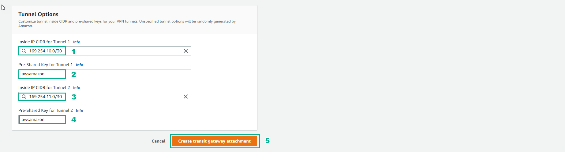
- Wait about 7 minutes, finish creating Transit gateway attachments
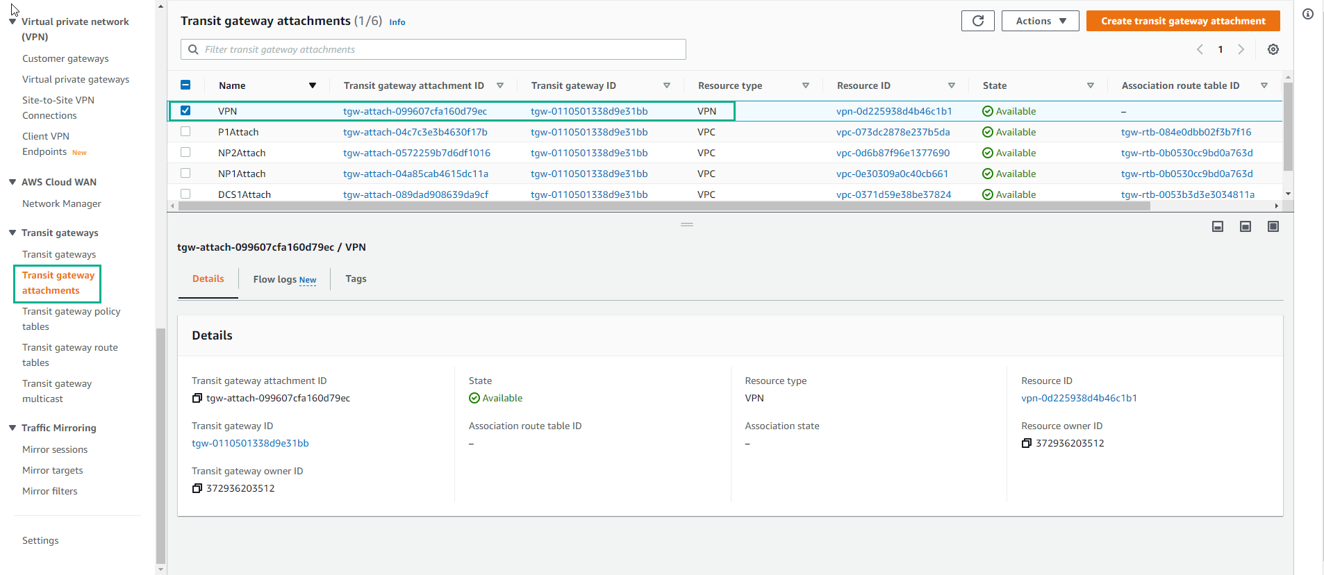
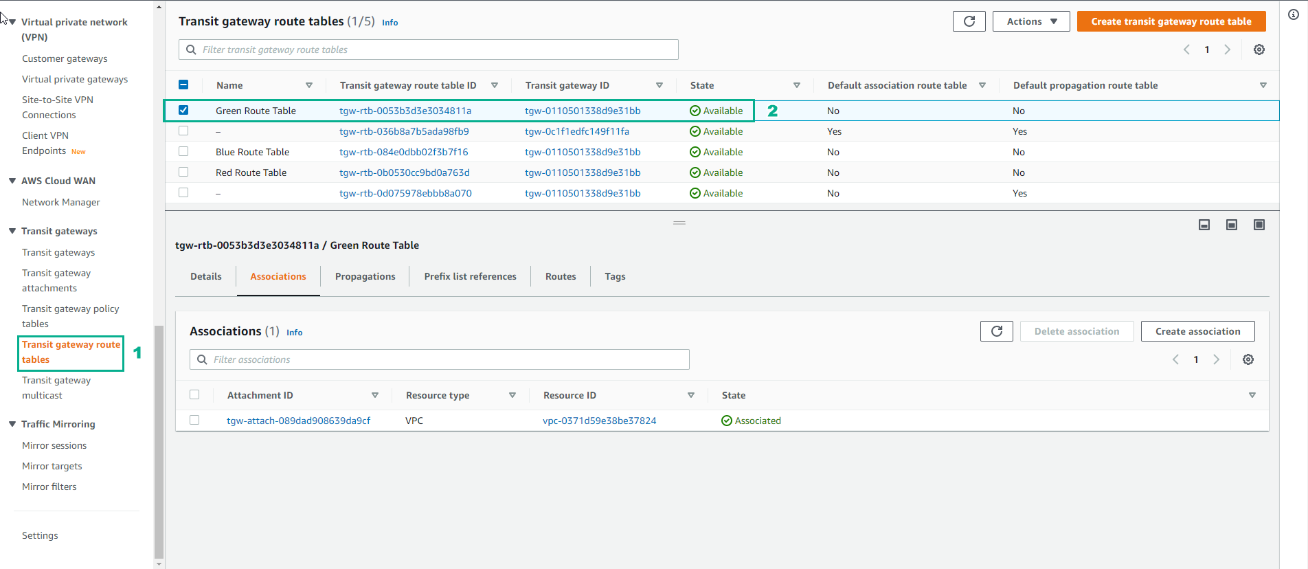
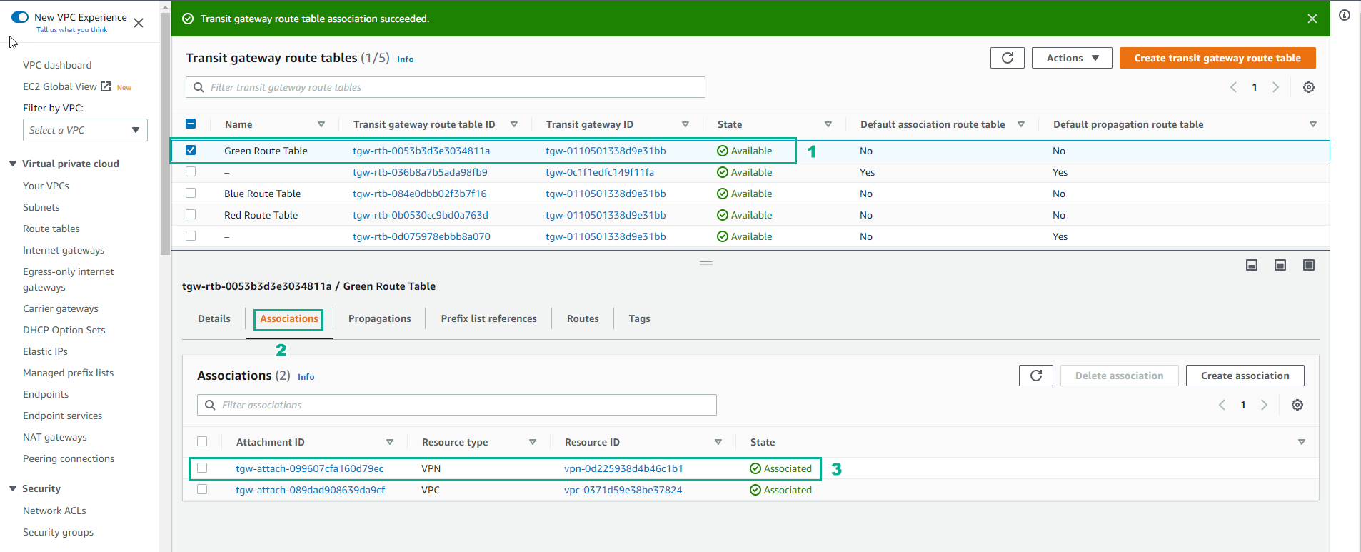
- Select Associations
- Select Create association
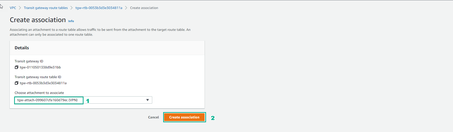
Associations mean that traffic coming from the outside towards the Transit gateway will use this route table. A routing lookup will take place in the TGW at this stage and the packet will be forwarded based on the information available within the “Routes” tab. Note: An attachment can only be Associated with one route table but a route table can have multiple associations.
- In the Create association interface, select Create association
- Completed Association
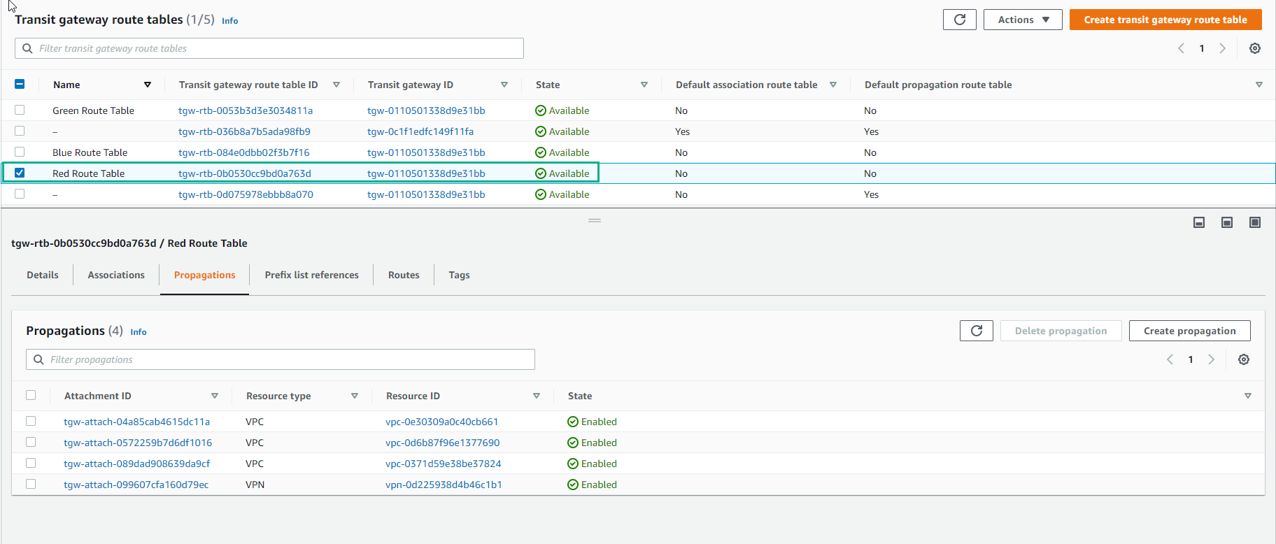
- Also in the Transit gateway route table interface
- Select Green Route Table
- Select Propagations
- Select Create propagations
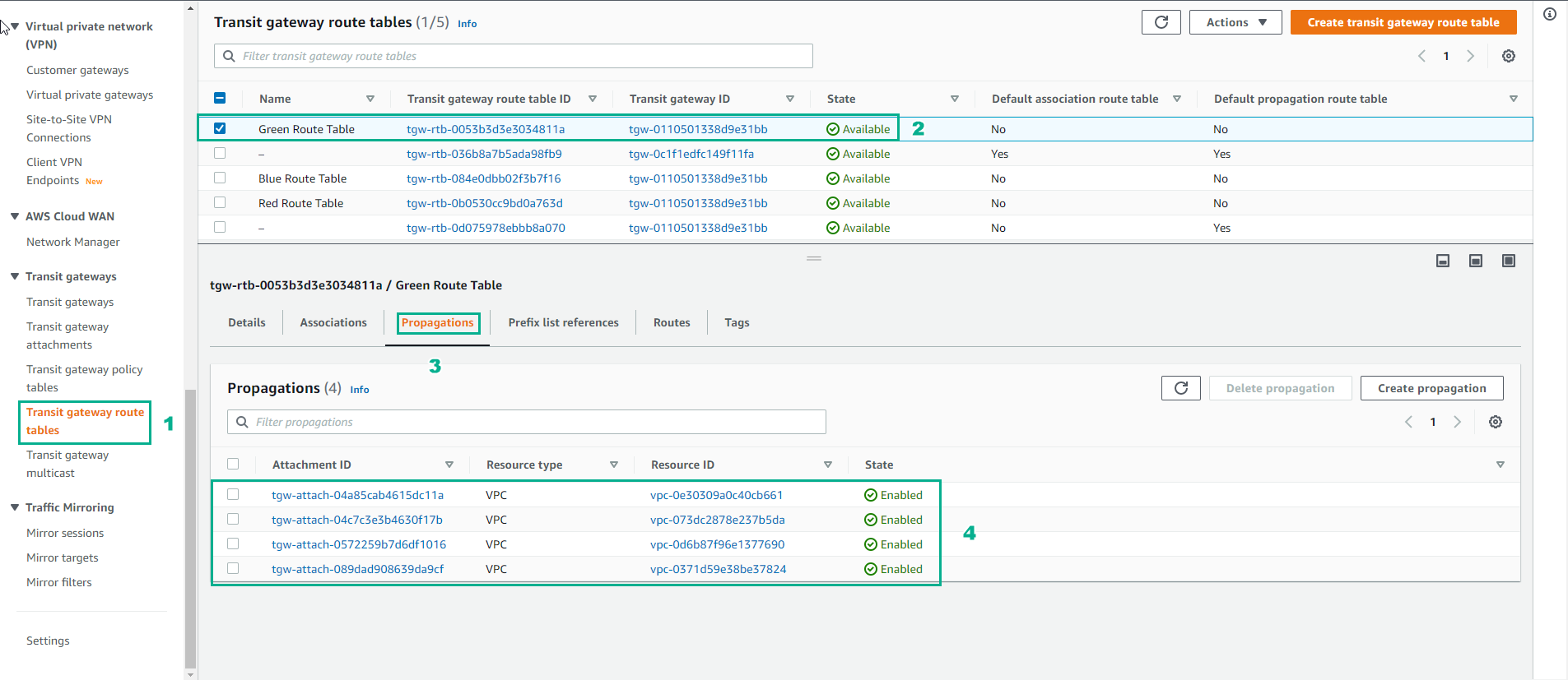
These are the attachments that propagate its prefixes into the route table (take it as an import into the route table). An attachment can propagate to multiple route tables. For this lab we want the datacenter addressing (the one reachable via the VPN connections) propagated to all of the route tables so the VPCs associated with each route table can route back to the datacenter.
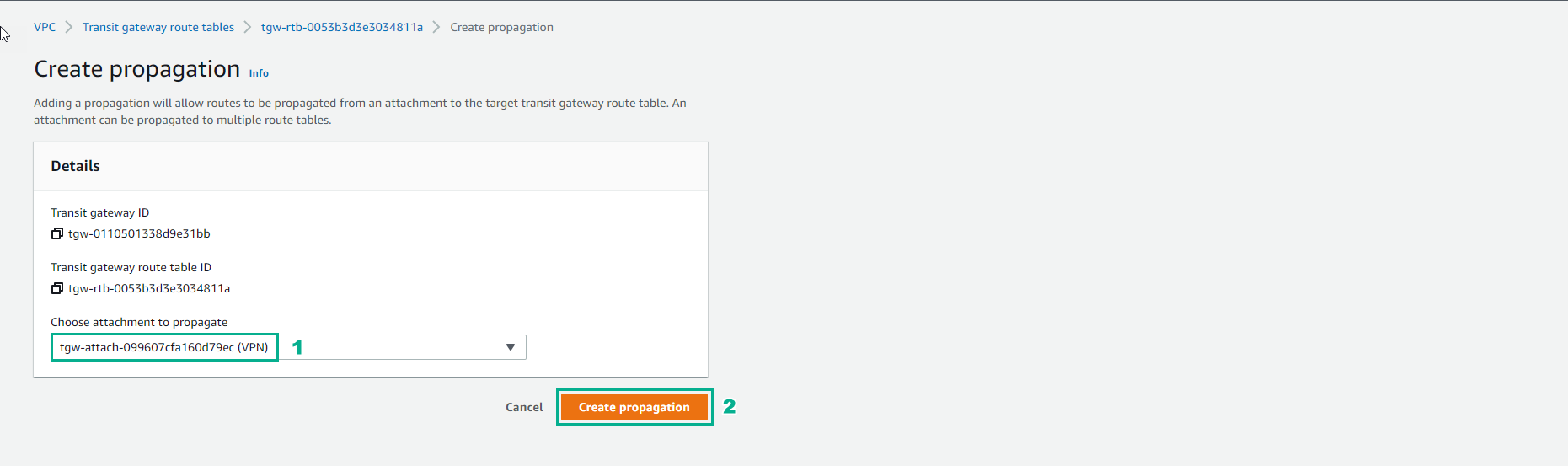
- In the Create propagation interface
- Select Create propagation
- Complete creation of propagation
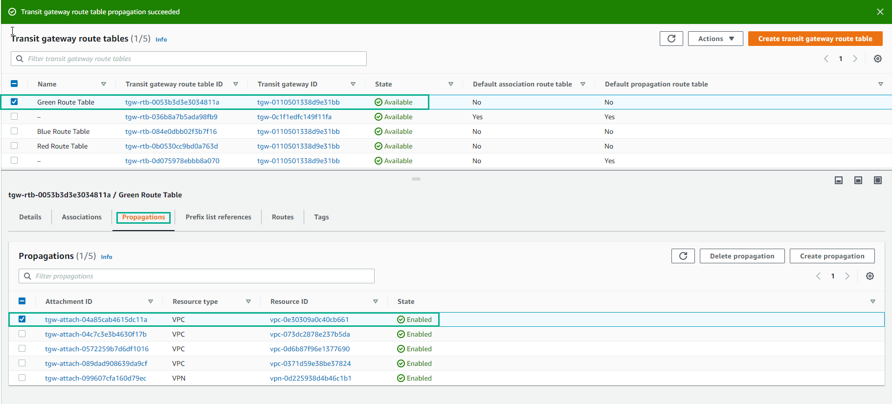
- Do the same Propagation creation for Red Route Table and Blue Route Table.
Take a look at each of the route tables and notice the tab Routes. You can see the routes that are propagated, as well as a static route table that was created for you by the CloudFormation template. That’s the default route (0.0.0.0/0) that will direct traffic destined for the Internet to the Datacenter Services VPC and ultimately through the NAT Gateway in that VPC. Note: there is also a route table with no name. This is the default route table. In this lab we do not intend to use it.
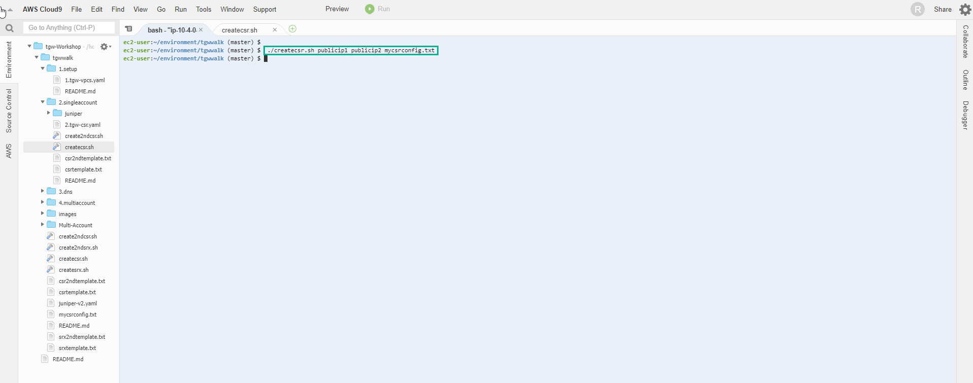
- Return to AWS Cloud9 interface. Now it’s time to get the other end ready and apply the configuration to the Cisco router so we can bring the VPN tunnels up. We will carry out this action generating the Cisco configuration file. In order to do that, go back to the Cloud9 browser tab. Using the two VPN public tunnel endpoints ips generated from the step above, cd to tgwwalk on the Cloud9 bash console and run the bash script appending the 2 ips and the name of the configuration file:
- We configure VPN to create a configuration file with the following command:
./createcsr.sh publicip1 publicip2 mycsrconfig.txt
-
We access Site-to-Site VPN Connections
- Select VPN Connection
- Select Tunnel details
- Because it is not configured, the status Down
- We use 2 IP addresses of Outside IP address
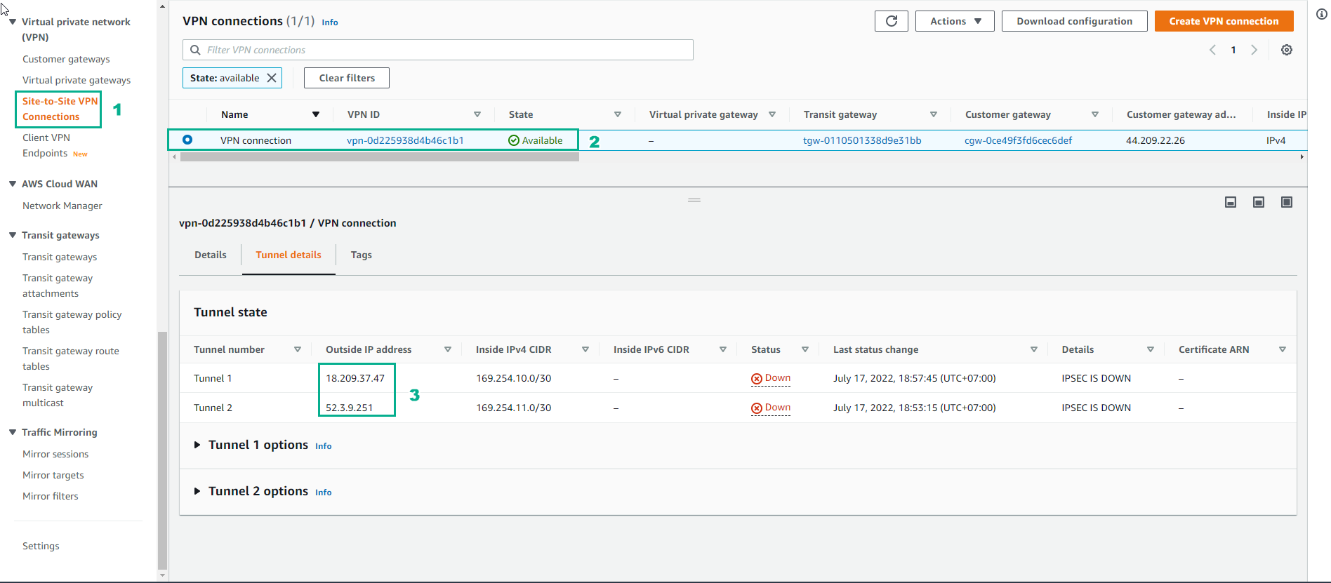
Note: The file ‘myscrconfig.txt’ is created to capture the output of the ‘createcsr.sh’ script and does not already exist in the repository. Make sure you put the ip address that lines up with Inside IP CIDR address 169.254.10.0/30 for ip1. This will result in a Cisco configuration file ready to be used
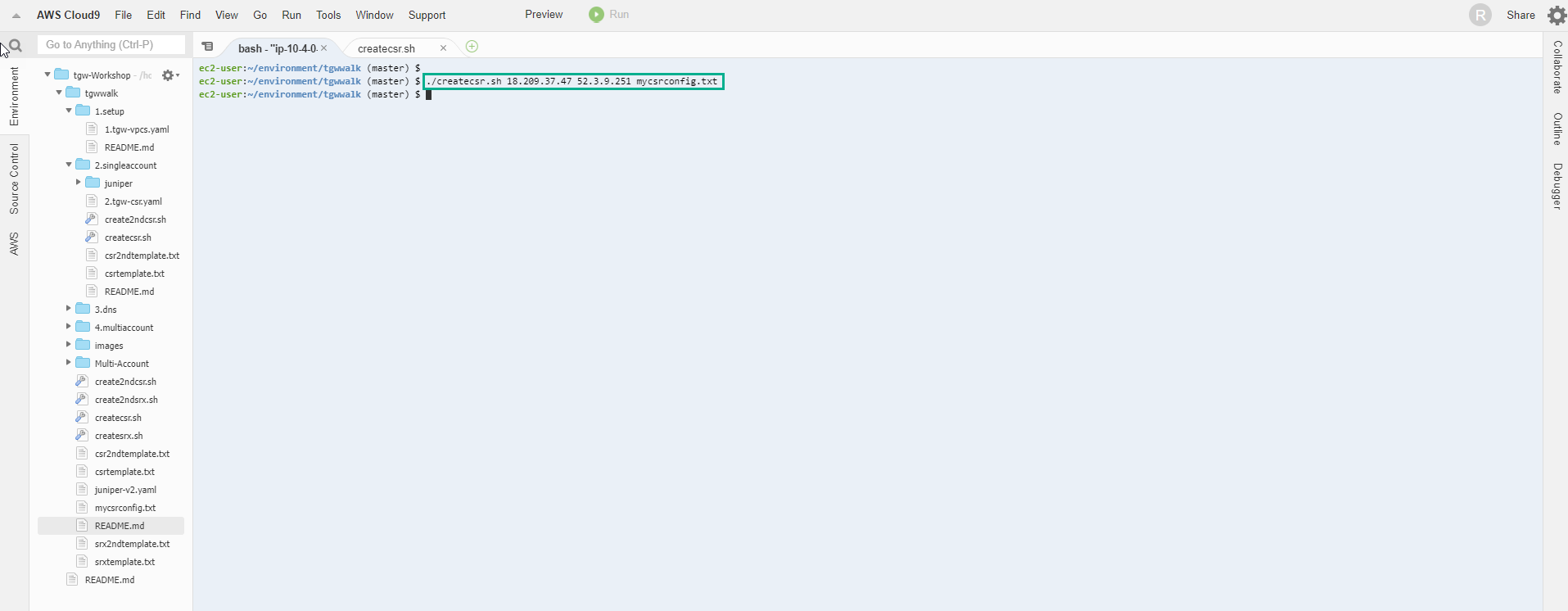
- Go back to the Cloud9 interface, replace the Public IP address and run the command to create the file mycsrconfig.txt
./createcsr.sh publicip1 publicip2 mycsrconfig.txt
Note: AWS generates starter templates to assist with the configuration for you on-premise router. For your real world deployments, you can get a starter template from the console for various device vendors (Cisco, Juniper, Palo Alto, F5, Checkpoint, etc). You can get those configurations via the “Download configuration” button within the Site-to-Site VPN Connections section explored before
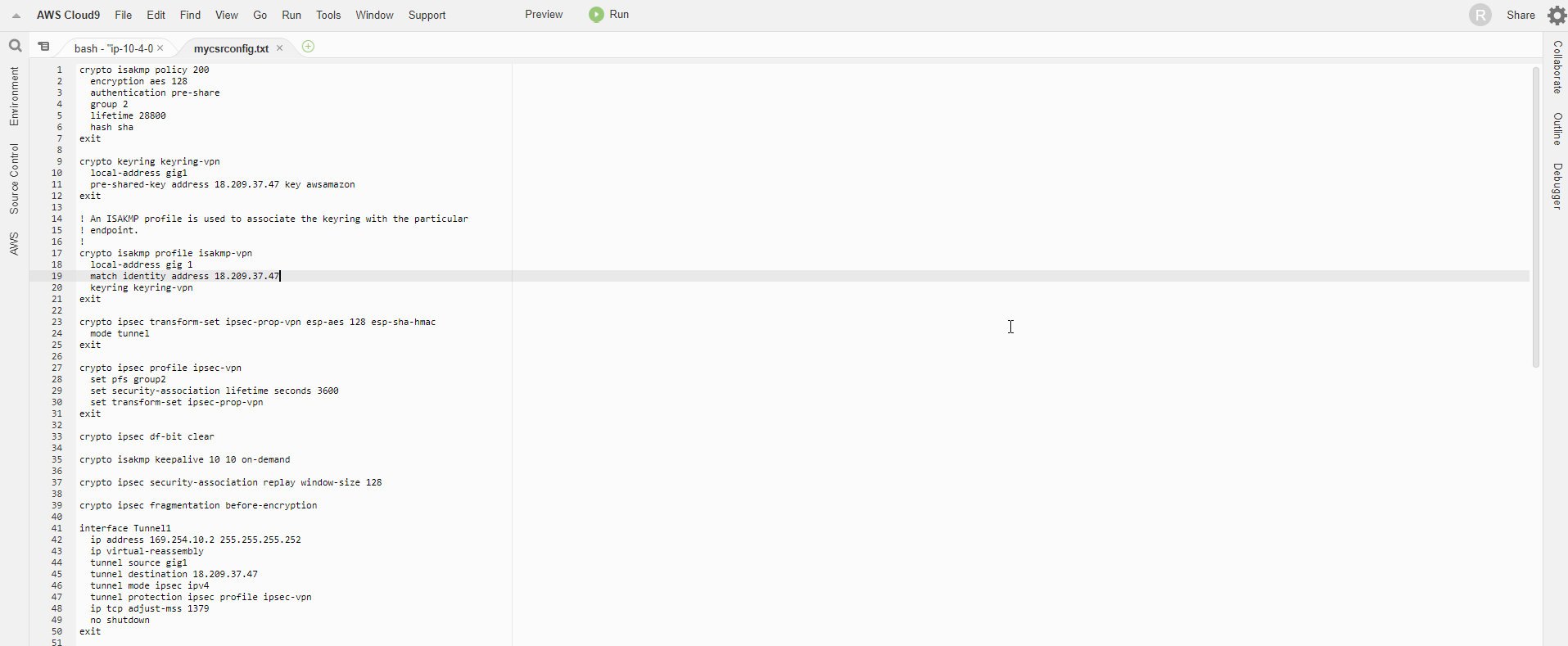
- We open the file mycsrconfig.txt to see the content of the VPN configuration.
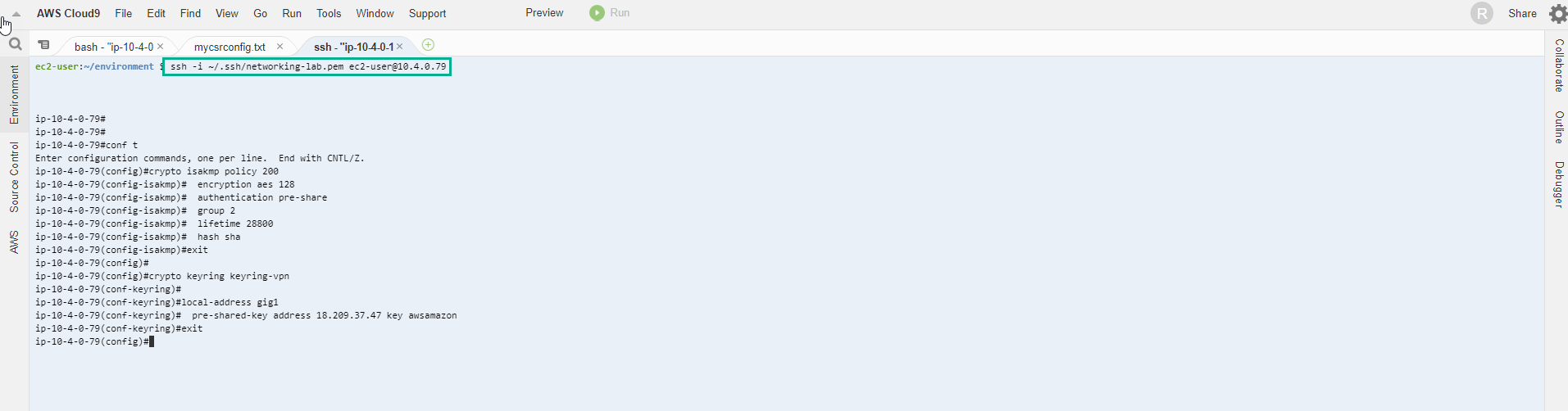
- Use command to start configuration
conf
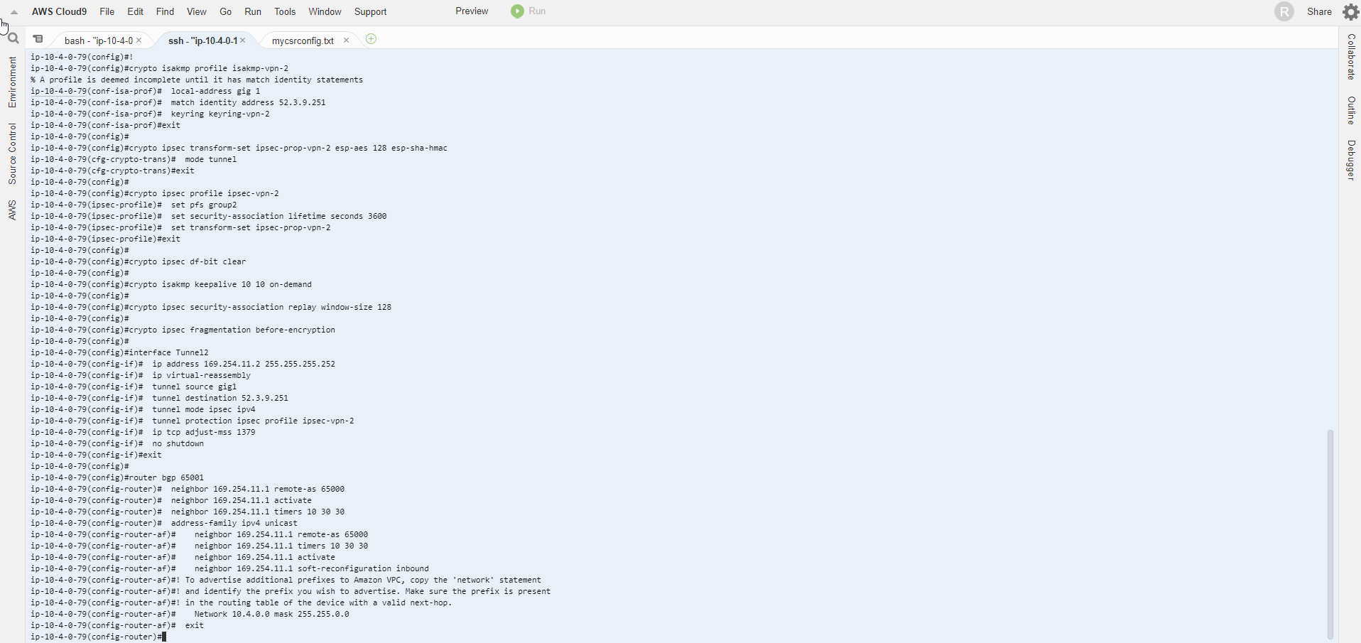
- Then copy all the commands in the file mycsrconfig.txt and paste them into the configuration.
- After configuration, enter exit to exit.
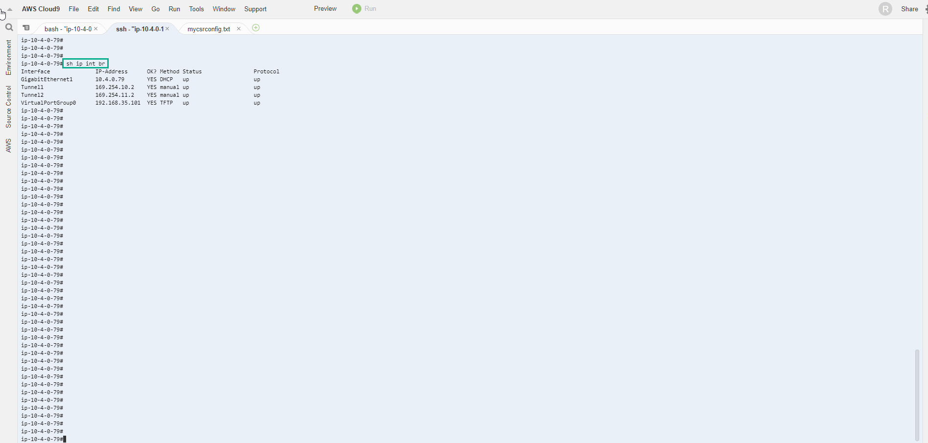
- To check the configuration successfully, execute the command
sh ip int br
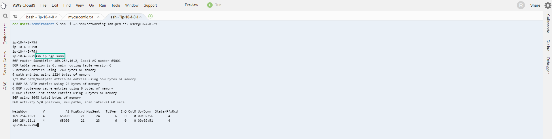
- Lets make sure we are seeing the routes on the Cisco CSR. first we can look at what BGP is seeing: show ip bgp summary. The most important thing to see is the State/PfxRcd (Prefixes received). If this is in Active or Idle (likely a neighbor statement is wrong: IP address, AS number) there is a configuration issue. What we want to see is a number. In fact if everything is setup correctly we should see 4 for each neighbor:
show ip bgp summary
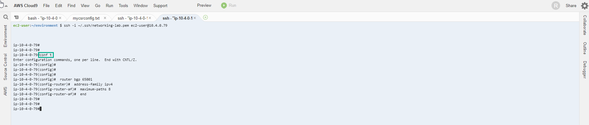
- Notice that there is only one next-hop address for each of the VPCs CIDRs, despite having 2 tunnels in place. This is the result of not using ECMP by default. We can fix this by allowing ECMP in the Cisco CSR router. Back in config mode we will set maximum-paths to 8 in our BGP router. Just drop these commands:
router bgp 65001
address-family ipv4
maximum-paths 8
end
- Execute the command sh ip route bgp again. Just to verify where those routes are coming from, we can take a look at the Green Route Table. Note: keep in mind that it’s under the VPC service and Transit Gateway Route Tables at the bottom of the left menu. There should be 5 routes listed.
sh ip route bgp
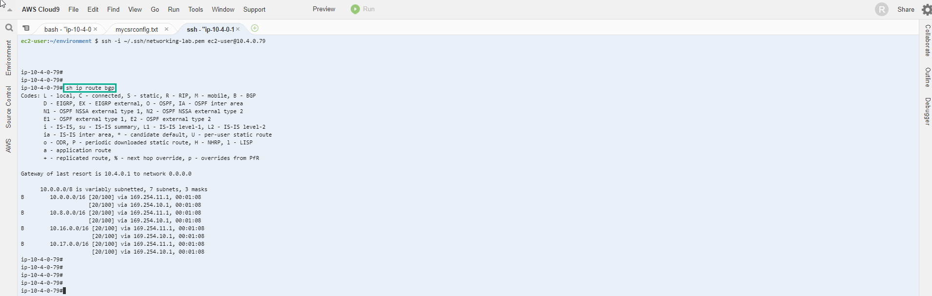
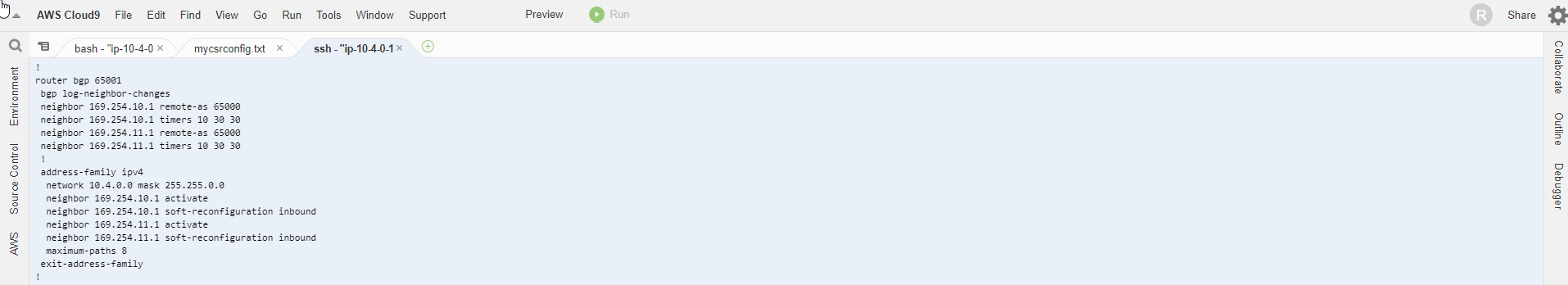
- As you might have guessed, route 10.4.0.0/16 is the VPC CIDR for the VPC DataCenter on which Cisco CSR operates. Cisco CSR is advertising this route to the Transit Gateway. You can actually test that by checking the router configuration with sh run and scrolling down to the BGP section:
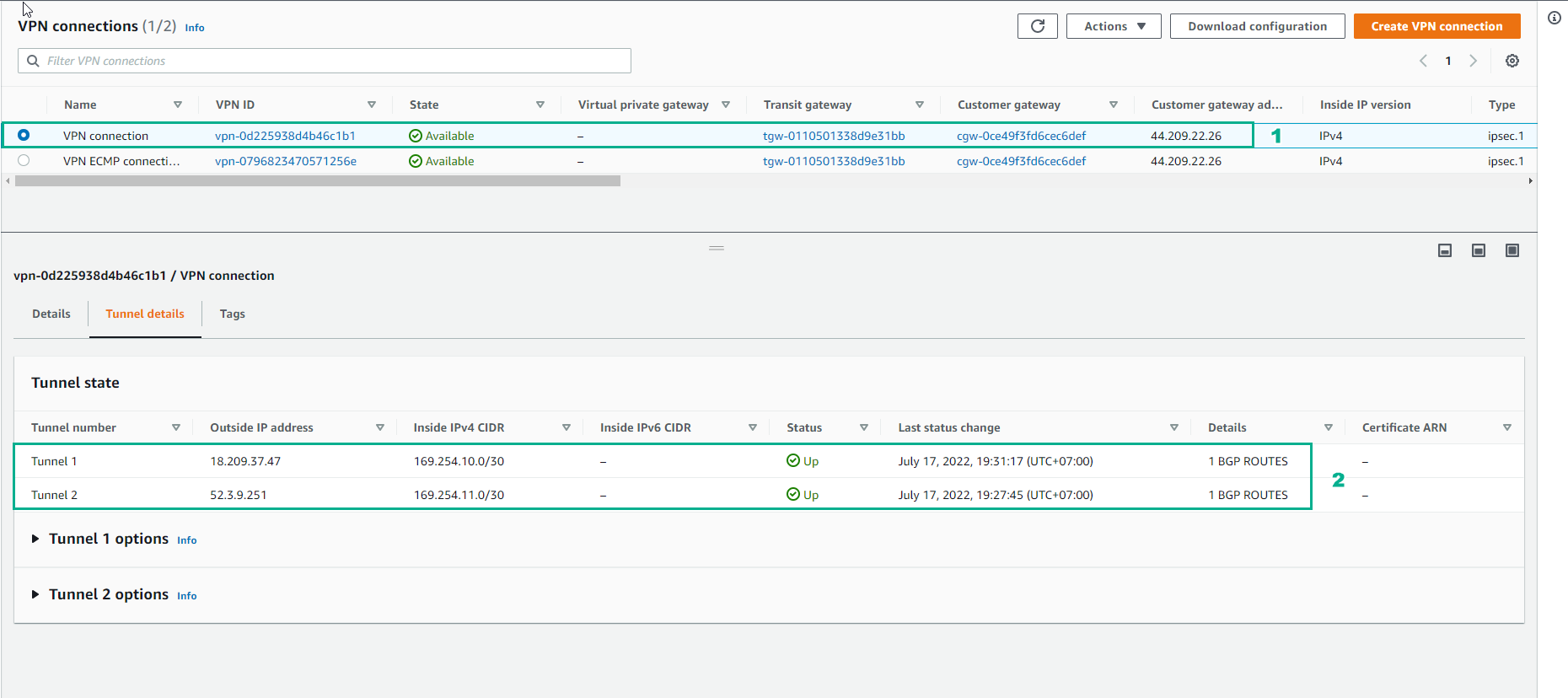
- Access to VPN Connections
- Select VPN Connection
- Select Tunnel details
- Two tunnels have changed state UP